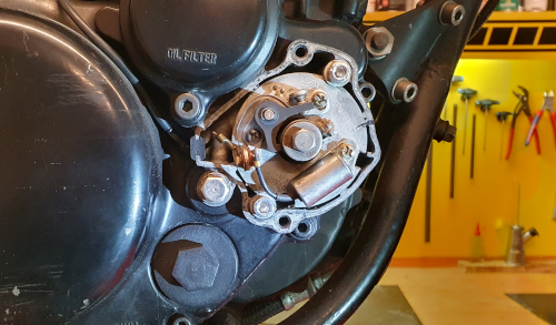
How to properly adjust the XT500 ignition
Important - check the basic condition of the individual parts before the ignition setting is made. Only with properly functioning components, the ignition can be optimally adjusted.
A. Check ignition advance:
Using a ignition strobe timing light, flash the magnet wheel at idle and check for smooth running and a steady indication. If, for example, the springs of the centrifugal governor are worn out, you will see a shaky stroboscopic image at idle (in extreme cases it will jump back from F to T at idle). Especially important: the mark for the maximum early adjustment should be exactly right when checking the ignition advance. If this is not the case and the adjustment is too early (too large and thus too far to the left), the centrifugal governor is worn.
Next, check the felt plate on the contact plate. It must be greased - if not, the cam may wear. Adjustment is no longer possible with a worn cam, as the opening times of the contacts are no longer correct.
With both faults, the ignition timing adjuster (centrifugal governor) should be replaced, repair is not possible. Unfortunately, the centrifugal governor is currently no longer available - in the event of a defect, we recommend switching to a CDI ignition.
B. Check capacitor:
Due to the very low capacitance, the XT ignition capacitor can only be measured with a special capacitance meter (0.22mF +/- 10%). With a multimeter, only the defect can be determined (diode test setting or resistance measurement): if the resistance is not infinite or if continuity is present, the capacitor is broken. However, a visual check is possible to check the function: the spark on the removed spark plug must be significantly weaker with the capacitor disconnected than with the capacitor connected.
C. Check contacts:
Inspect the contacts for pitting and cratering. Contacts can be reworked with fine sandpaper.
Now the first actual ignition adjustment procedure can take place - the static adjustment:
The first thing to do is to make sure that the contact plate screws are tightened. Turn the engine until the contacts are fully open. Adjust the contact gap to 0.35-0.45 mm using a feeler gauge. The contacts are screwed onto the contact plate via slotted holes. Loosen one screw (if necessary both screws - if they are screwed very tight) that holds the contacts in place. Do not loosen screw too far to ensure easy adjustment. Adjustment is made by twisting the contacts on the base plate (using a screwdriver in the small grooves). Now tighten the screws and only then check the adjustment.
D. Static ignition timing adjustment:
There are two different methods here, both have their convinced followers and opponents. Our tip - try both and decide for yourself.
Place tin foil, cigarette paper or a 0.03mm gauge between the contacts. Pull carefully on the paper/feeler gauge while turning the engine (apply SW 19mm to the magnet wheel, unscrewing the spark plug helps !), when you reach the F-mark on the magnet wheel the paper/feeler gauge should just slip out of the contacts. Clamp a test lamp or light bulb between the positive pole of the battery and the leaf spring of the moving contact. If the contacts are closed, the lamp lights up. Turn the magnet wheel towards F; if it is set to F, the lamp should just go out.
Attention: An optimum ignition setting is rarely achieved with the static setting. Therefore, after the static setting, the dynamic setting should be made with a ignition strobe timing light.
E. Dynamic ignition timing adjustment:
The ignition strobe timing light should be designed for 6V or a high quality 12V version. In addition, there are also vehicle power independent ignition strobe timing lights.
Connect the power supply and the induction pickup according to the manufacturer's description. Start the engine (should be no problem after good static adjustment) and flash the magnet wheel/early adjustment.
Adjustment starts: 2250 +/- 150 rpm
Adjustment ends: 3000 +/- 200 rpm
Adjustment range: 20° +/- 3°
Advanced ignition: 27° +/- 3°
F. Ignition coil control:
Primary coil: 0.75 ohms - here you measure between ground bracket and Japan plug (or 6.3mm flat plug tongue)
Secondary coil: 5.7 kOhm - here you measure between end of ignition cable (without spark plug connector) and ground bracket
.
G. Checking the ignition source coil and lighting coil:
This refers to the two coils on the alternator stator under the magnet wheel. These are very rarely defective. We recommend a continuity test (diode test setting on the multimeter) on the alternator's 4-way connector to rule out a defect (ground fault). Lighting coil: continuity should be measurable between ground (blank spot on the engine) and the white or yellow cable. The yellow cable is the tap for the front/rear light (regulated AC circuit), the white cable is the tap for the rectifier. Ignition coil: continuity should be measurable between ground (bare spot on the engine) and black cable.
Goto product category:
Contact Ignition XT500
 The store will not work correctly in the case when cookies are disabled.
 Der Shop wird nicht korrekt funktionieren, wenn Cookies deaktiviert sind.
 La boutique ne fonctionnera pas correctement si les cookies sont désactivés.